蜂鸟E200 RISC |
您所在的位置:网站首页 › 蜂鸟h7pro 48T错误代码 › 蜂鸟E200 RISC |
蜂鸟E200 RISC
|
【取指过程】
【概述】
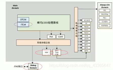
源代码的Hierarchy如下: E200处理器采用两级流水线,取指为第一级,执行、访存、写回、交付均在第二级。 在第一级需要利用BPU进行分支预测。 BPU分支预测三种情况:1、条件分支 2、直接跳转 3、间接跳转 PC:用于指令地址的生成,同时在一些PC相关的指令也会用到。 处理器产生一个PC,这个请求会给到地址判断和总线控制(ICB总线是和AMBA差不多的一款自定义的总线结构,自己看看就行),对读取PC的请求进行解析。指令可以存在ITCM里面,也可以存在总线上的Flash里,所以IR的来源是经过一个MUX来选择的。 指令进来以后,首先对这个指令进行简单的译码,指令译码之后,一部分用于下个PC的生成,同时放到IR里面进行寄存,送到执行单元里面进行进一步的执行,比如运算加减等等。 当前PC和下一个PC都会有寄存器记录下来。 如果BPU猜错了,就要flush流水线。 指令可以存在ROM里、QSPI-Flash里、ITCM里 ITCM有64k的空间,一些应用领域足够了 ROM的空间比ITCM要大一些,在RTL里,这个ROM是个假的 Hierarchy图示: 深红色的是指令可以存放的位置。 ifetch所有的地址访问都需要经过ift2icb模块的处理,这是一个总线公共的接口。 64k空间不够的时候,挂在Bus Interface上面。 一般的做法是把外部的搬到ITCM里面再运行,可以用多级存储体的结构来理解,一级cache、二级cache、三级cache、硬盘。 ITCM的端口是64位的,这意味着我们取出32位的指令一次可以取2条,16位的一次可以取4条。(当然也有可能出现跨边界的现象,必须取两次才能取完,用了一个状态机实现)。 模块代码解析: 【Mini-Decode】这是一个纯组合逻辑的译码器,它是EXU中的Decoder的一个缩小版,略去了一些输出信号。作用是帮助BPU判断指令的类型,进行分支预测。 端口列表: 可以看到,代码中就是简单地例化了exu中的decoder 分支预测,这也是个纯组合逻辑(除了一个小小的寄存器) 还有一个要注意的地方是,e200对x1寄存器进行特别的加速,因为这个寄存器常用来存放子程序的返回地址: 在程序调用完以后,return回调入的入口,这个东西编译器做了一个优化措施: link寄存器可以是x1或者是x5,但是在e200中,只对x1做优化 汇编程序执行的时候,执行到JAL指令的大部分情况下(调用子程序),调用入口的下一个PC会放到x1寄存器中(当然也可以放到别的地方去,但是x1用的比较多),所以对x1进行特殊的加速。 当rs1为x1寄存器的时候,需要考虑数据的RAW相关性,如果没有RAW相关性的时候,说明这个x1目前没有写。 (1)指令执行的cycle不是一个定长的,在EXU中,加减乘除的周期数可能是不一样的,这就涉及到一个什么时候会写入寄存器的一个判定问题。于是就用到了OITF这玩意儿,在exu中会详细介绍。总之要加速的话必须要OITF为空。 (2)IR寄存器中正在执行的指令不是以x1作为目标寄存器的。 如果存在数据相关性,那么就hold up IFU。 当rs1为其它寄存器的时候,就要慢一些了,因为没有对它们进行单独的加速。只要EXU里头有正在执行的东西,它就不能预测rs1对应的xn会不会被写入。 【PC生成】(在e203_ifu_ifetch.v中)
要考虑指令不对齐的情况,用一个状态机来实现 这个接口模块几乎是IFU里最复杂的一部分了 这里状态机的写法值得一学 在胡振波写的所有的代码中,除了底层的D触发器以外,没有用到一个always case语句用不具有优先级的assign语句实现MUX(如果有优先级的话需要额外的面积开销) 状态转移用例化实现 一些注释: /// The itfctrl scheme introduction // // The instruction fetch is very tricky due to two reasons and purposes: // (1) We want to save area and dynamic power as much as possible // (2) The 32bits-length instructon may be in unaligned address // // In order to acheive above-mentioned purposes we define the tricky // fetch scheme detailed as below. // /// // Firstly, several phrases are introduced here: // * Fetching target: the target address region including // ITCM, // System Memory Fetch Interface or ICache // (Note: Sys Mem and I cache are Exclusive with each other) // * Fetching target’s Lane: The Lane here means the fetching // target can read out one lane of data at one time. // For example: // * ITCM is 64bits wide SRAM, then it can read out one // aligned 64bits one time (as a lane) // * System Memory is 32bits wide bus, then it can read out one // aligned 32bits one time (as a lane) // * ICache line is N-Bytes wide SRAM, then it can read out one // aligned N-Bytes one time (as a lane) // * Lane holding-up: The read-out Lane could be holding up there // For examaple: // * ITCM is impelemented as SRAM, the output of SRAM (readout lane) // will keep holding up and not change until next time the SRAM // is accessed (CS asserted) by new transaction // * ICache data ram is impelemented as SRAM, the output of // SRAM (readout lane) will keep holding up and not change until // next time the SRAM is accessed (CS asserted) by new transaction // * The system memory bus is from outside core peripheral or memory // we dont know if it will hold-up. Hence, we assume it is not // hoding up // * Crossing Lane: Since the 32bits-length instruction maybe unaligned with // word address boundry, then it could be in a cross-lane address // For example: // * If it is crossing 64bits boundry, then it is crossing ITCM Lane // * If it is crossing 32bits boundry, then it is crossing System Memory Lane // * If it is crossing N-Bytes boundry, then it is crossing ICache Lane // * IR register: The fetch instruction will be put into IR register which // is to be used by decoder to decoding it at EXU stage // The Lower 16bits of IR will always be loaded with new coming // instructions, but in order to save dynamic power, the higher // 16bits IR will only be loaded when incoming instruction is // 32bits-length (checked by mini-decode module upfront IR // register) // Note: The source of IR register Din depends on different // situations described in detailed fetching sheme // * Leftover buffer: The ifetch will always speculatively fetch a 32bits // back since we dont know the instruction to be fetched is 32bits or // 16bits length (until after it read-back and decoded by mini-decoder). // When the new fetch is crossing lane-boundry from current lane // to next lane, and if the current lane read-out value is holding up. // Then new 32bits instruction to be fetched can be concatated by // “current holding-up lane’s upper 16bits” and “next lane’s lower 16bits”. // To make it in one cycle, we push the “current holding-up lane’s // upper 16bits” into leftover buffer (16bits) and only issue one ifetch // request to memory system, and when it responded with rdata-back, // directly concatate the upper 16bits rdata-back with leftover buffer // to become the full 32bits instruction. // // The new ifetch request could encounter several cases: // * If the new ifetch address is in the same lane portion as last fetch // address (current PC): // ** If it is crossing the lane boundry, and the current lane rdout is // holding up, then // ---- Push current lane rdout’s upper 16bits into leftover buffer // ---- Issue ICB cmd request with next lane address // ---- After the response rdata back: // ---- Put the leftover buffer value into IR lower 16bits // ---- Put rdata lower 16bits into IR upper 16bits if instr is 32bits-long // // ** If it is crossing the lane boundry, but the current lane rdout is not // holding up, then // ---- First cycle Issue ICB cmd request with current lane address // ---- Put rdata upper 16bits into leftover buffer // ---- Second cycle Issue ICB cmd request with next lane address // ---- Put the leftover buffer value into IR lower 16bits // ---- Put rdata upper 16bits into IR upper 16bits if instr is 32bits-long // // ** If it is not crossing the lane boundry, and the current lane rdout is // holding up, then // ---- Not issue ICB cmd request, just directly use current holding rdata // ---- Put aligned rdata into IR (upper 16bits // only loaded when instr is 32bits-long) // // ** If it is not crossing the lane boundry, but the current lane rdout is // not holding up, then // ---- Issue ICB cmd request with current lane address, just directly use // current holding rdata // ---- Put aligned rdata into IR (upper 16bits // only loaded when instr is 32bits-long) // // // * If the new ifetch address is in the different lane portion as last fetch // address (current PC): // ** If it is crossing the lane boundry, regardless the current lane rdout is // holding up or not, then // ---- First cycle Issue ICB cmd reqeust with current lane address // ---- Put rdata upper 16bits into leftover buffer // ---- Second cycle Issue ICB cmd reqeust with next lane address // ---- Put the leftover buffer value into IR lower 16bits // ---- Put rdata upper 16bits into IR upper 16bits if instr is 32bits-long // // ** If it is not crossing the lane boundry, then // ---- Issue ICB cmd request with current lane address, just directly use // current holding rdata // ---- Put aligned rdata into IR (upper 16bits // only loaded when instr is 32bits-long) // 四个状态 状态0:IDLE,表示没有取指请求 状态1:如果非对齐,需要发起两次读取操作的第一次读取状态 状态2:第一次和第二次读取之间的等待状态 状态3:如果非对其需要发起两次读取操作的第二次读取状态
|
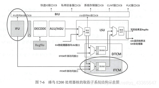 画圈的是有关取值的两个重要模块 IFU:Instruction Fetch Unit 取指单元 ITCM:紧耦合存储器,指配置一段较小容量(几十KB)的存储器(通常是静态存储器),用来存储指令,在物理上离处理器核很近而专属于处理器核。优点是实现非常简单,容易理解,且能保证实时性。
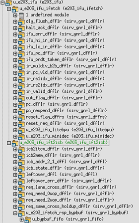 示意图:
示意图: 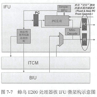

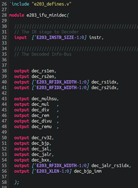 译码出来的信息有: 是否有rs1 rs2 rs1,rs2的index 一些乘除法相关的,具体作用需看RISC-V指令集的标准 一些跟分支跳转指令有关的 无条件间接跳转/分支指令jalr的源寄存器 立即数(分支/跳转的偏移量)
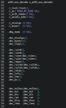
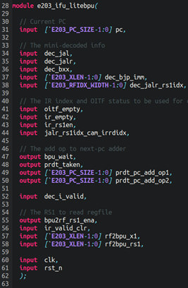 输入是一些来自mini-decoder的译码信号,指示这条指令属于哪条分支跳转指令 以及数据相关性的判定,如果数据有相关,那么就不能进行流水线操作 具体的三种类型,以及代码的注释,胡振波的书上写的很详细了。 这边的bpu_wait跟ifu_o_valid有关,这个valid信号直接送到exu上进行握手。 当有数据相关的时候,bpu_wait会拉高,说明要等。


 输入输出结构图(粉色是输入,棕色是输出,可以大致看出数据流)


【本文地址】
今日新闻 |
推荐新闻 |